

Telecommunications Container
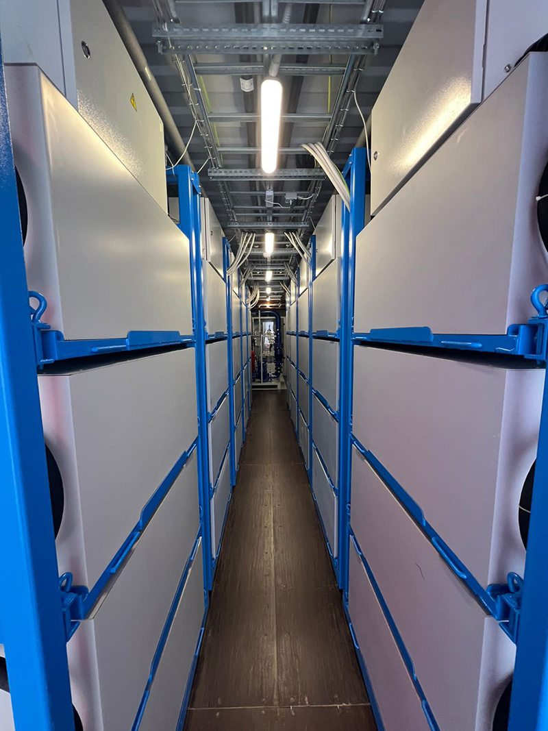
Within the immersive container, the foundational components revolve around a cluster of immersive cooling-enabled telecommunications racks, precisely ten in number. These racks are meticulously aligned along the longitudinal axis of the container, meticulously integrated into the triad of power supply, communication systems, and the intricate machinery governing equipment cooling within the container. These racks stand as the linchpin of our data center infrastructure, orchestrating the symphony of computational prowess while ensuring optimal thermal conditions for peak performance.


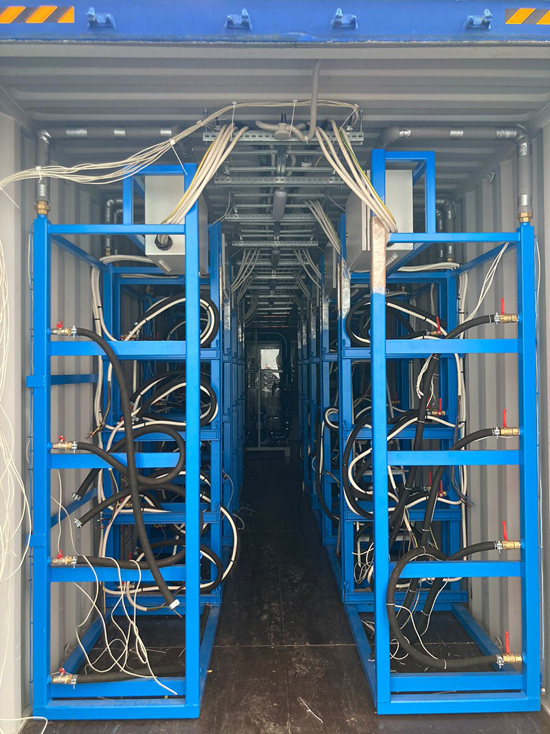
Telecommunications Rack
The telecommunications rack serves as a pivotal component designed for the accommodation of computational modules. It plays a multifaceted role in our infrastructure, facilitating the organization of a local computing network among the modules, establishing connectivity with the external Internet network, and, notably, serving as a conduit for the immersive cooling of these modules through the use of immersion liquid. This versatile and integral element ensures the seamless operation of our data center environment.
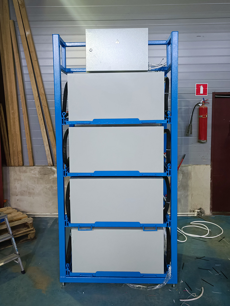
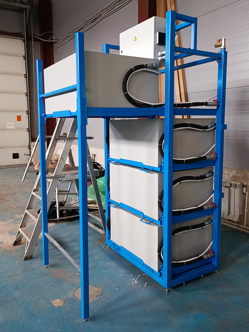
Telecommunications Rack Components
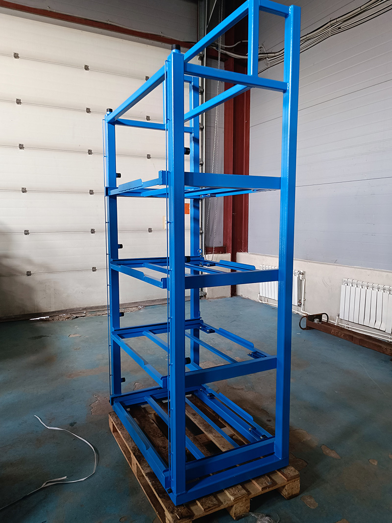
The telecommunications rack is a meticulously engineered assembly comprising the following key elements:
- Steel Frame: A robust steel framework provides structural integrity and support.
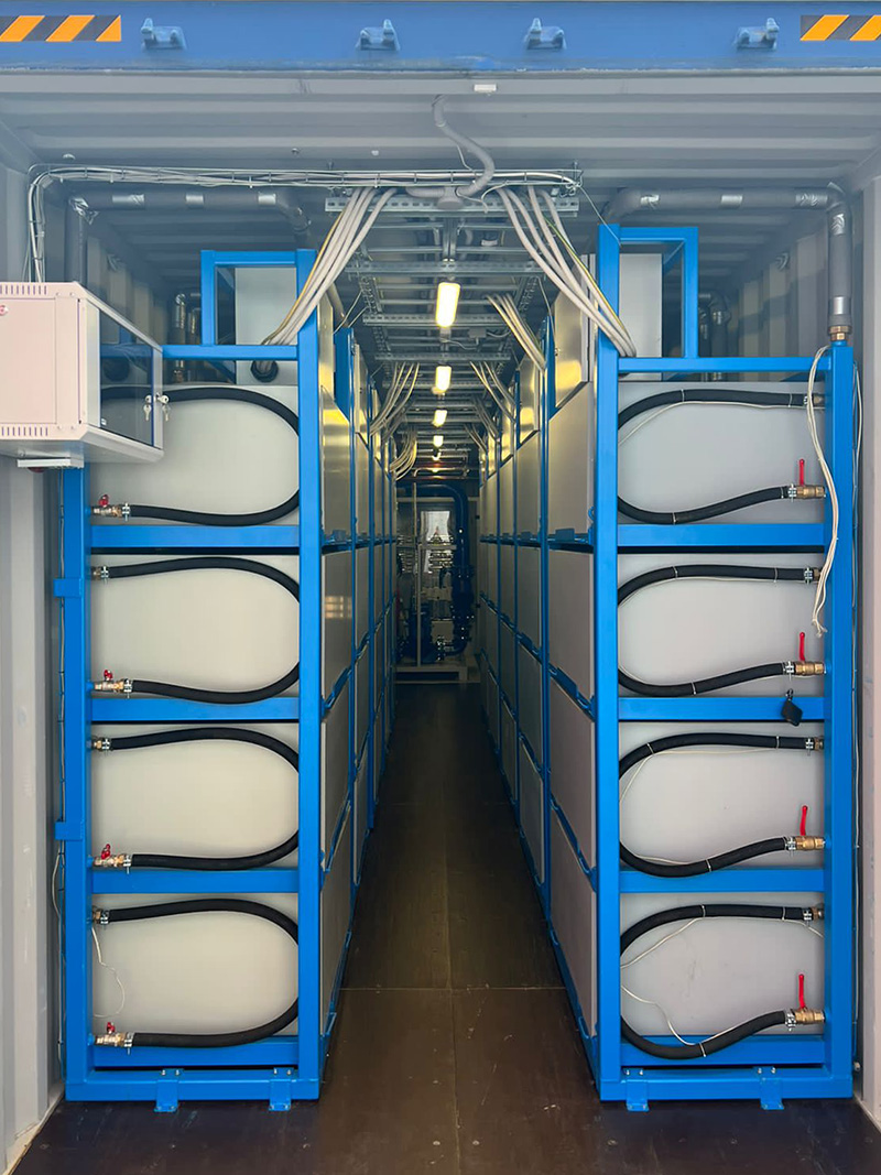
- Composite Material Cells: The rack features four compartments crafted from composite materials, each meticulously designed for the housing of computational modules. These cells serve as the foundation for the secure placement of computing components.
- Input Distribution Panel: An input distribution panel resides within the rack, equipped with protective circuit breakers and switches. This panel efficiently manages the distribution of electrical power and network connectivity.
Each computational module cell is constructed from 10mm-thick sheets of STЭФ-1 fiberglass-reinforced epoxy laminate material. This material exhibits exceptional anti-corrosive properties and thermal insulation capabilities. The internal space within each cell is thoughtfully partitioned into two sections. One accommodates computational modules, while the other houses a copper brazed-plate heat exchanger and a circulation pump, contributing to efficient cooling.
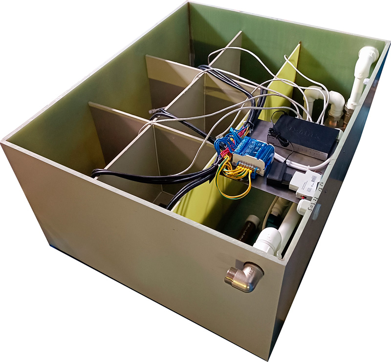
For the electrical supply of the computational modules within each cell, an electrical distribution panel is thoughtfully incorporated, complete with a comprehensive set of wiring. Additionally, an unmanaged 8-channel 10/100 Mbps switch is securely mounted on the panel, facilitating the establishment of a computing network interconnecting the modules and the external network. This meticulously designed telecommunications rack serves as the backbone of our data center infrastructure, ensuring the seamless operation of our computational environment while prioritizing thermal efficiency and reliability.
Container Equipment Electrical Supply Scheme
The electrical supply system for the container equipment is a well-structured setup, consisting of a Voltage Regulating Unit (VRU) and an intricate network of cable lines. The connection between the VRU and the external power source is established through cables with a cross-section of 4x185 mm², three-phase 0.4 kV. The VRU is designed to accommodate the connection of three lines of this cable. The VRU is configured in a dual-section format, comprising two hypothetical sections, and incorporates the following components:
- Two main switches with a shared drive, each possessing a nominal current rating of 1250 A.
- Ten automatic circuit breakers rated at 250 A, equipped with independent trip units at a nominal voltage of 220 V, 50 Hz.
- Automatic circuit breakers dedicated to specific functions, including a 63 A breaker for pumps, 25 A breakers for air conditioners, 16 A breakers for lighting, 16 A for the power supply system (OPS), 25 A for sockets, along with three backup lines rated at 63 A, 25 A, and 16 A.
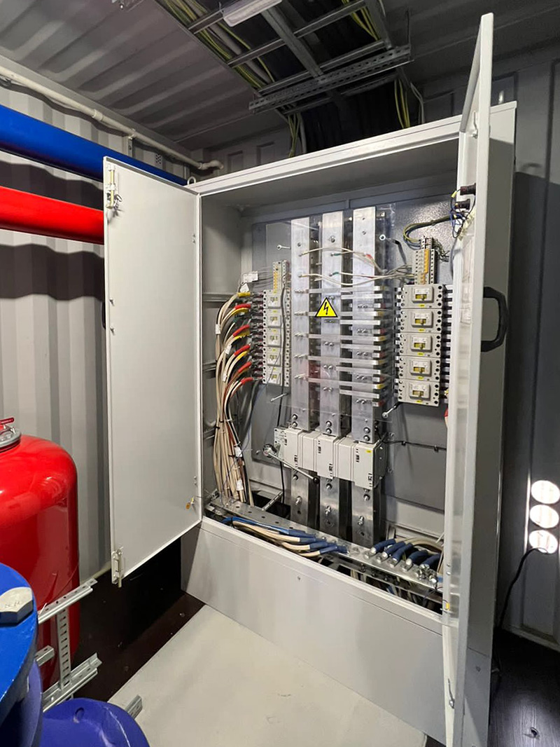
This meticulously configured VRU, with its assortment of circuit protection devices and redundant lines, serves as the backbone of the container's electrical supply system, ensuring robust and reliable power distribution to the equipment within the container.
Hydraulic Cooling System for the Container
The hydraulic cooling system within the container is a meticulously engineered setup designed to maintain optimal operating temperatures. It comprises the following components:
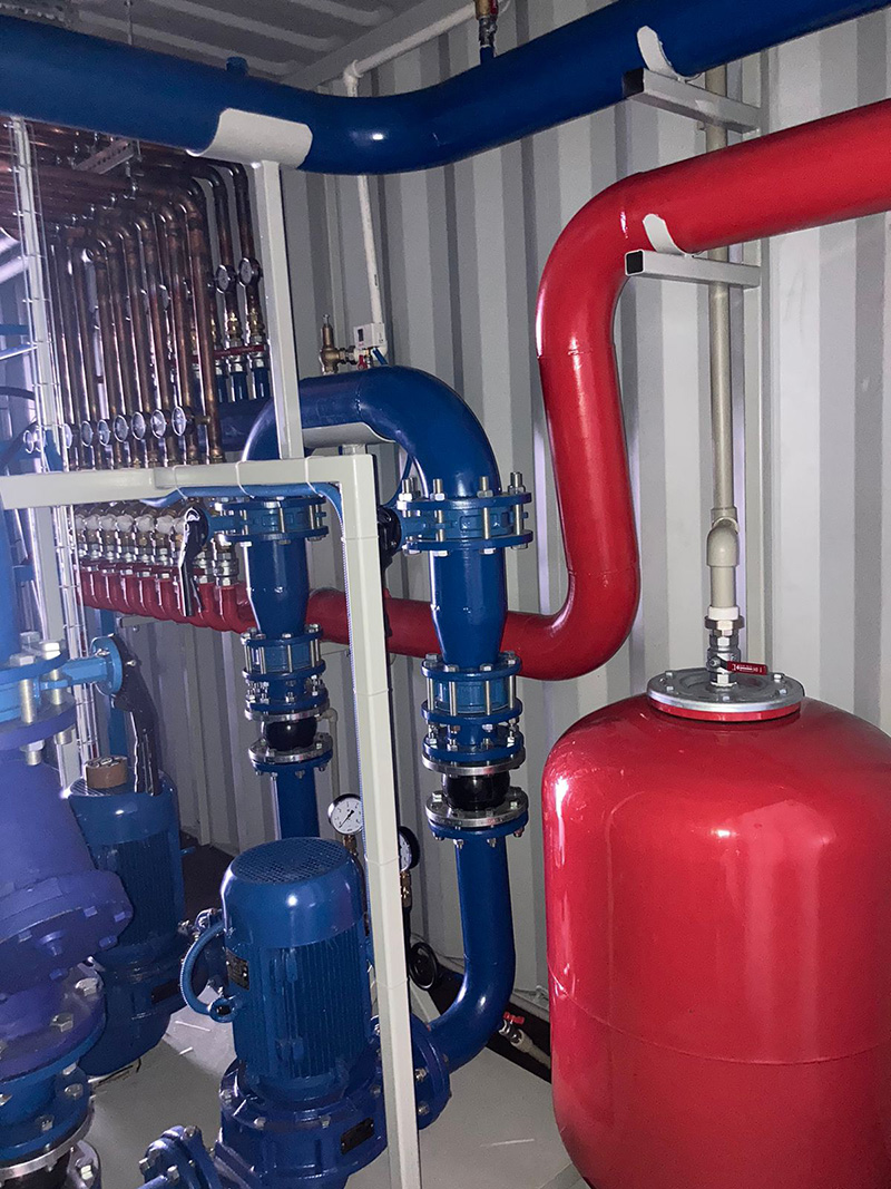
- Pipelines: The system features pipelines constructed from 159 mm diameter pipes for both the high-pressure (cold) and low-pressure (hot) lines. These pipes extend towards the front wall of the container and terminate with flanges for connection to the dry cooling tower pipelines.
- Pumps: The hydraulic system employs a dual-stage configuration featuring two single-stage end-suction pumps of type TKF-I 125-250 operating at 1450 rpm, each with a power rating of 10.01 kW at 50Hz or similar specifications. The pump assemblies include flexible couplings, check valves, isolation valves, filters, and pressure gauges on the suction and discharge lines.
- Pump Distribution: The pump assemblies are interconnected through 133 mm diameter pipes. Within the container, a 200-liter vertical expansion tank is installed on the high-pressure line, serving as a membrane-type expansion vessel. Additionally, an air vent and a safety relief valve (Icma 1") are installed on the high-pressure line outside the container, acting as protective mechanisms in case of pressure exceedance.
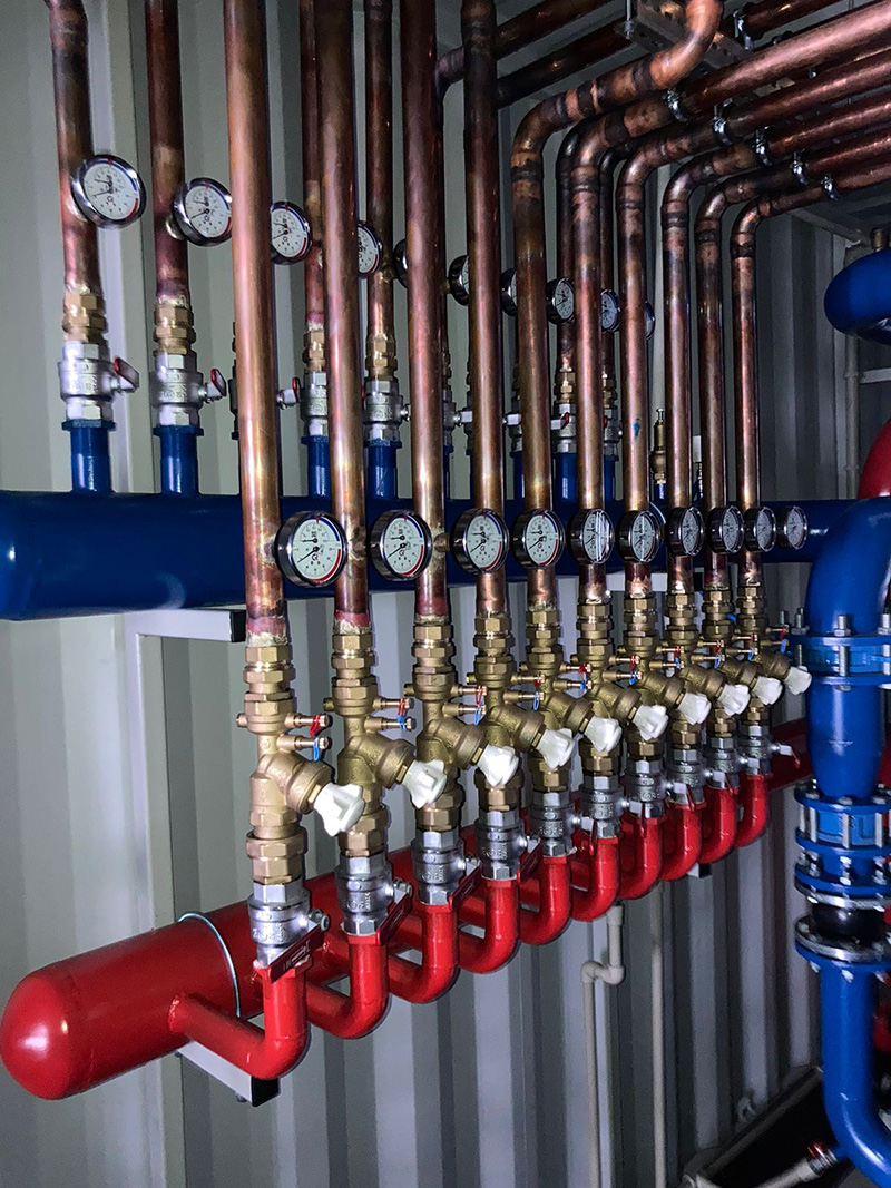
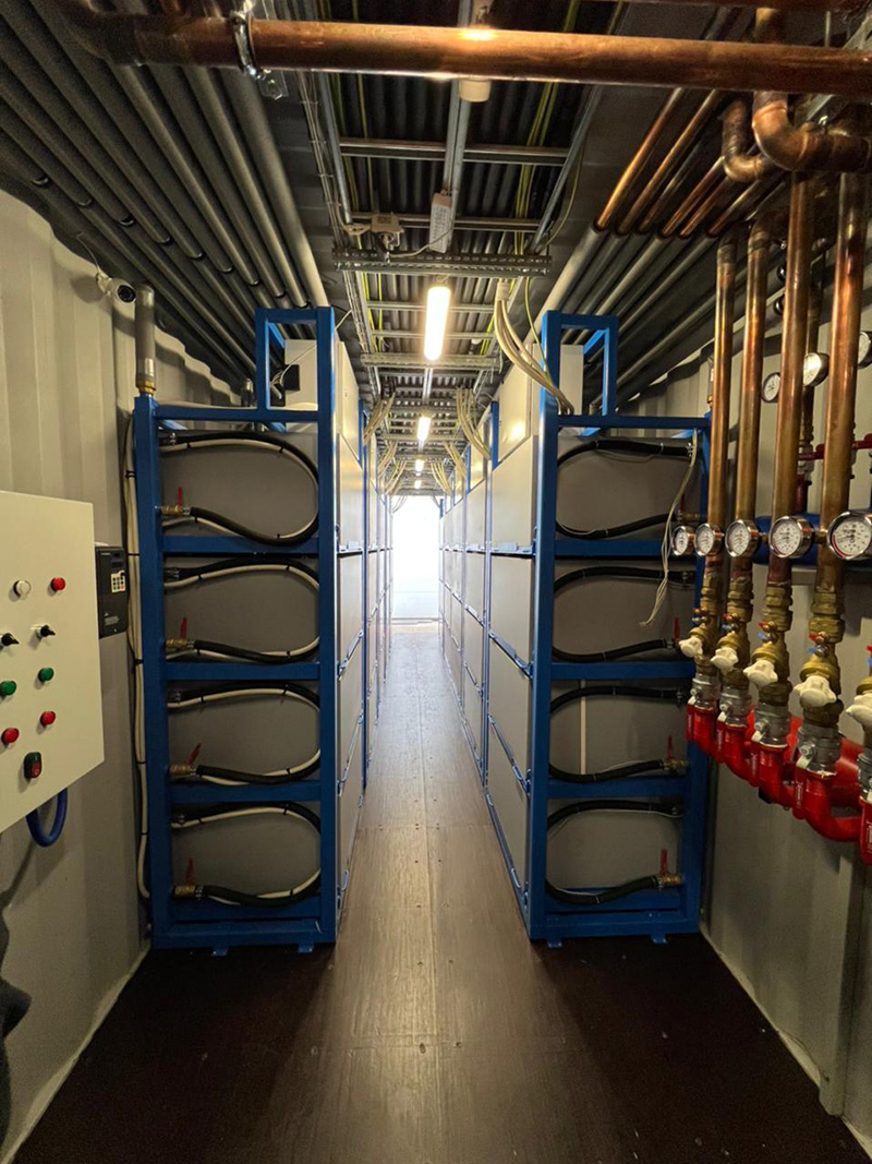
- Manifold Assembly: After exiting the pump module, the cold water lines from the racks are converged into a cold water manifold equipped with ten outlets. The manifold is color-coded blue. Each outlet from the cold water manifold is fitted with an isolation valve and a pressure gauge.
- Hot Water Collector: Subsequently, the return lines from the racks are gathered into a hot water manifold with ten inlets. The manifold is color-coded red. Each inlet to the hot water manifold is equipped with an isolation valve, a static balancing valve without stubs (R206BY017), and a pressure gauge.
- Pressure Control: A pressure relay (Danfoss KPI35 RANGE -0.2...8 bar DIFF 0.5...1.5 bar) is installed on the high-pressure manifold as a safeguard against deviations in the coolant pressure from the specified parameters. Additionally, a digital pressure sensor is situated on the high-pressure manifold for pump control.
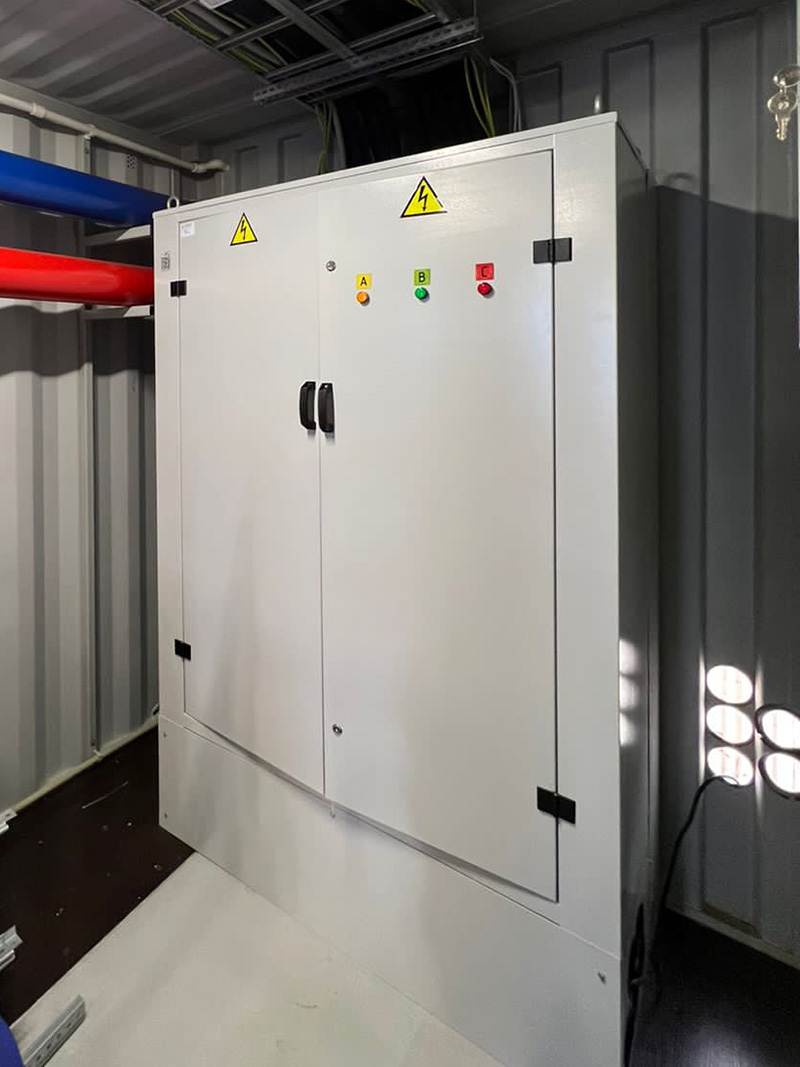
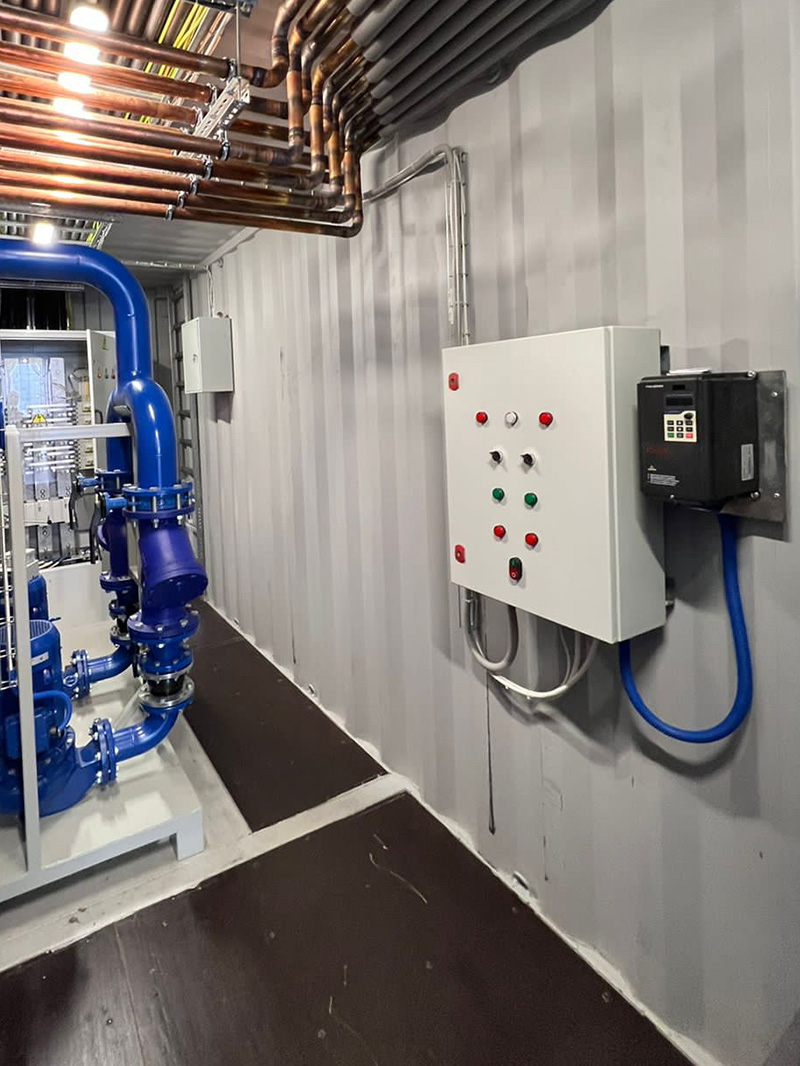
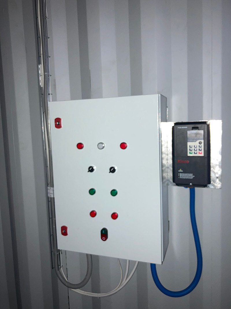
- Pump Control Cabinet: The pump control cabinet is positioned within the hydraulic equipment zone, adjacent to the entrance. The cabinet's front panel features power selection switches for one of the two feeders via "0," voltage presence indicators, a pump selection switch, a "Start/Stop" button for the pump variable frequency drive (VFD), and an illuminated non-latching button for engaging the auxiliary pump, which includes a lockout based on the maximum pressure sensor. Pump control is implemented using a Programmable Logic Controller (PLC). The variable frequency drive is appropriately matched to the pump motor's power rating. Additionally, the control cabinet incorporates automatic circuit breakers rated for the nominal consumption current.
Security and Fire Alarm System (SFAS)
The Security and Fire Alarm System (SFAS) is strategically located within the hydraulic equipment zone, adjacent to the MV switchgear. It boasts the following features:
- Uninterruptible Power Supply (UPS): The SFAS is equipped with a 1000VA Uninterruptible Power Supply (UPS) with automatic self-recovery capabilities. The UPS ensures continuous electrical power supply to the system.
-
Sensors: SFAS incorporates a comprehensive array of sensors, including:
- Two heat and smoke detectors (75 degrees).
- Two magnetic contacts (reed switches) on both the front and side doors.
- Two volumetric motion sensors, one in each zone.
- A key card reader.
- GSM Controller: SFAS is outfitted with a GSM controller featuring an antenna modem that is externally mounted on the container. This component facilitates remote monitoring and control.
- Audio-Visual Signaling: Inside the container, an audio-visual signaling system is installed to alert personnel in case of security breaches or fire hazards.
- Key Card Reader: A key card reader is positioned on the exterior of the small door for secure access control.
Communication System (Internet)
The telecommunication cabinet is configured as a standard 19-inch rack, with a height and depth of 400 mm, featuring a transparent door. Its location is designated in front of the left row of racks, adjacent to the side door. This cabinet accommodates a network switch and a video surveillance system.
Video Surveillance System
The video surveillance system operates around the clock, 24/7. It encompasses a 4-channel video recorder, situated within the telecommunication cabinet. The system records in high definition (HD) quality, storing data on both an internal HDD and a cloud server. The internal HDD has the capacity to retain video recordings for a minimum duration of 48 hours from all four cameras.
- In the hydraulic equipment zone, a camera with a 180-degree field of view is installed.
- In the rack zone, a camera with an 85-degree field of view is installed, directed along the row of racks from the center of the container towards the end gates.
- Two external cameras oversee the perimeter and entrances of the container.
Lighting System
The container's lighting system comprises six linear LED luminaires, each measuring 600 mm, evenly distributed along the container's length. Splash-proof light switches control the illumination. Additionally, two separate battery-powered LED luminaires serve as emergency lighting fixtures.
Climate Control System
The climate control system utilizes split-system air conditioners for efficient temperature regulation. In the rack zone, a 24 nominal unit is installed, situated 100 mm from the ceiling above the front entrance of the container and directed along the passage between the racks. In the hydraulic equipment zone, a 12 nominal unit is installed, positioned 100 mm from the ceiling above the side entrance of the container.
Condensate from the air conditioners is routed through pipes and exits through an opening in the floor beneath the container. External units of the air conditioners are mounted on the external end wall of the container. A power selector switch on the SFAS control cabinet allows for power distribution between the air conditioners via "0".
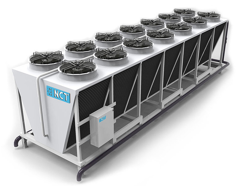
Dry Cooling Tower (Dry Cooler)
For cooling the immersion coolant in the container's cooling system, a V-shaped dry cooler with a cooling capacity of 1.5 MW is employed. Dry coolers are widely used in various industrial applications to cool process fluids.
Key Advantages of Dry Coolers:
- Minimal requirement for makeup water, as the fluid circulates within a closed-loop system. This is especially advantageous when using glycol-based solutions.
- Simplified design leads to extended maintenance intervals and reduced maintenance costs.
- Compact dimensions allow for installation in tight spaces, inaccessible to traditional evaporative coolers.
- Cost-effective equipment with economical operational expenses, leading to rapid return on investment.
- Reliable fans with low noise levels and minimal energy consumption.
- Absence of moisture and fluid evaporation.
- Corrosion-resistant casing made from galvanized steel with a protective polymer coating.
The dry cooler is connected to the container's hydraulic system through steel pipes with flanged connections and shut-off valves. A control cabinet for the dry cooler is installed on the exterior of the container and serves the following functions:
- Regulation of fan speed (for economical operation during winter).
- Setting temperature sensors for each circuit.